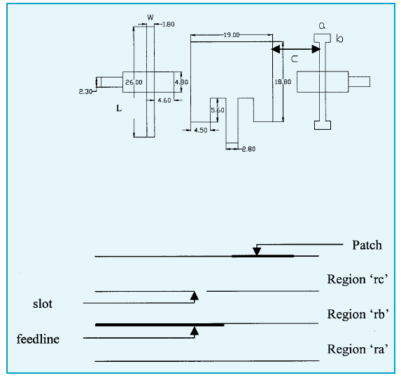
Fig 1 (a) Schematic of the multi-frequency patch antenna (b) Side view of the
antennas and feed
| IETE TECHNICAL REVIEW, Vol 23, No 6, 2006 |
358 |
Fig 1 (a) Schematic of the multi-frequency patch antenna (b) Side view of the
antennas and feed
the slot layer. Feed for slot is isolated from patch by ground layer. Thickness and permittivity of the substrate is determined as a trade off between crosspolar radiation and bandwidth [2]. Bottom ground layer is required to avoid radiation in undesired direction as slot has the characteristic of bidirectional radiation. Complete assembly is sharing a common aperture with slot and patch radiating in presence of each other without affecting their individual radiation pattern. 2.1. Design of Patch Antenna At C-Band Microstrip patch is selected as radiating element at C-band. In direct fed patch configuration, input impedance of the patch is very high as a result of which the width of the microstrip line feeding the patch becomes very small. Typically width of 200 ohms line is 0.167 mm which with relative permittivity of 2.2 is very difficult to print accurately. Therefore inset fed patch geometry is used. In this geometry input impedance of the patch can be controlled by moving the feed line inside the patch. Microstrip line is fed inside the patch at the point of 100 ohms input impedance |
The various parameters have been optimized through analysis using Ansoft Ensemble software. The final dimension of the patch which yields the desired RF performance in the presence of the X-band slot cut in the ground plane of the patch is shown in Fig 1. 2.2. Design of Slot Antenna At X-Band At X-band, printed slot is employed as radiating
element. This slot is cut in the ground plane of C-band
patch and it is fed by a microstrip line below a dielectric |