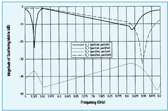
Fig 2 Simulated Return loss at C-band and X-band shared aperture single microstrip antenna (using
rectangular slot)
| B K PANDEY et al : DUAL FREQUENCY |
359 |
The advantage of the dog bone slot is that, it is compact as compared to
rectangular slot. But for dual polarized antenna still
rectangular shape slot is a preferred option as it yields
better cross-polar performance. The left most corner 3. SIMULATED RESULTS OF SINGLE ELEMENT Figure 2 shows the simulated return loss
performance of single patch at C band and single slot
at X-band. Return loss bandwidth of 120 MHz is
observed from the graph at 5.35 GHz while the return
loss is 900 MHz at center frequency 9.6 GHz for
VSWR ratio of 2:1. Simulated gain of single patch at
C-band is 7.1 dBi at 5.35 GHz. At 9.6 GHz simulated
gain of single slot is 4.5 dBi. Figure 3 shows the |
Similarly linear decrease in ‘a’ and ‘b’ dimensions of
dog-bone slot results in upper side frequency shift in
return loss performance. These results are shown in
Figs 4 and 5. Similarly length ‘l’ and width ‘w’ of the
rectangular slot is also varied and its effect on return
loss performance is shown in the Figs 6 and 7. It is 4. DESIGN OF 2X2 PLANAR ARRAY Single element is duplicated in both X and Y directions to form planar array. 2×2 patch elements are combined using microstrip lines. 2×2 slots are fed by an asymmetric stripline feed network. Spacing between patch elements is 0.8 λ, in both X and Y directions. Inter element spacing between patches is optimized for maximum gain of array. |
Fig 2 Simulated Return loss at C-band and X-band shared aperture single microstrip antenna (using rectangular slot)